In Part 3 of this series, I looked at the JTAG scan path of the ASSET ScanLite demo board, and explored some of the fundamentals of IEEE 1149.1. This week, I do some fault insertion on the scan path, and see how that is detected by boundary scan.
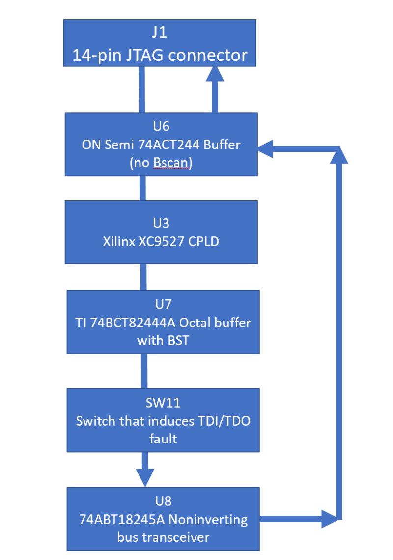
For reference’s sake, the scan path of the ScanLite demo board looks like this:
Note that there is a switch, SW11, in the scan chain, that lies between U7 (a simple octal buffer), and U8 (a bus transceiver).
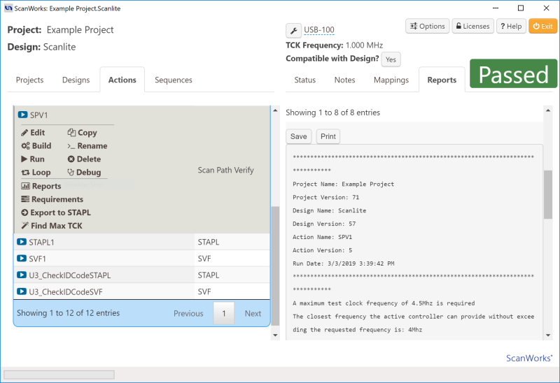
If we just run a scan path verification (SPV) on this design, we get the following display:
The run log for this action is below:
********************************************************************************
Project Name: Example Project
Project Version: 71
Design Name: Scanlite
Design Version: 57
Action Name: SPV1
Action Version: 5
Run Date: 3/3/2019 3:39:42 PM
********************************************************************************
A maximum test clock frequency of 4.5Mhz is required
The closest frequency the active controller can provide without exceeding the requested frequency is: 4Mhz
Test clock frequency has been changed to 4Mhz for this action only
*** No precondition file present ***
*** Starting DeviceID & Bypass DR scan only test… ***
IDCODE for Device U8 in tap 1 PASSED
Expected data: 00010000000000000101000000101111
Measured data: 00010000000000000101000000101111
BYPASS for Device U7 in tap 1 PASSED
Expected data: 0
Measured data: 0
IDCODE for Device U3 in tap 1 PASSED
Expected data: XXXX1001010100000100000010010011
Measured data: 00101001010100000100000010010011
*** Starting IR Capture test… ***
IR Capture test PASSED for TAP 1
*** Starting BYPASS test… ***
BYPASS test PASSED
*** Starting IDCODE test… ***
IDCODE for Device U8 in tap 1 PASSED
Expected data: 00010000000000000101000000101111
Measured data: 00010000000000000101000000101111
BYPASS for Device U7 in tap 1 PASSED
Expected data: 0
Measured data: 0
IDCODE for Device U3 in tap 1 PASSED
Expected data: XXXX1001010100000100000010010011
Measured data: 00101001010100000100000010010011
*** Starting Boundary Length test… ***
Boundary Length test PASSED for TAP 1.
Test completed successfully
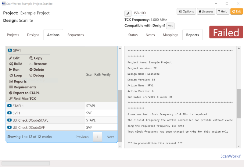
Now, by putting SW11 to “open”, we are able to create a fault in the scan chain, between devices U7 and U8. When we do this, the display changes:
The new run log is below:
********************************************************************************
Project Name: Example Project
Project Version: 72
Design Name: Scanlite
Design Version: 58
Action Name: SPV1
Action Version: 6
Run Date: 3/3/2019 3:54:39 PM
********************************************************************************
A maximum test clock frequency of 4.5Mhz is required
The closest frequency the active controller can provide without exceeding the requested frequency is: 4Mhz
Test clock frequency has been changed to 4Mhz for this action only
*** No precondition file present ***
*** Starting DeviceID & Bypass DR scan only test… ***
IDCODE for Device U8 in tap 1 PASSED
Expected data: 00010000000000000101000000101111
Measured data: 00010000000000000101000000101111
BYPASS for Device U7 in tap 1 FAILED
Expected data: 0
Measured data: 1
IDCODE for Device U3 in tap 1 FAILED
Expected data: XXXX1001010100000100000010010011
Measured data: 11111111111111111111111111111111
Scan chain failure between U7 and U8
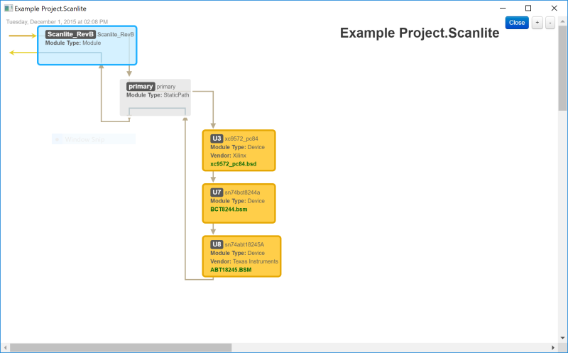
Now, this is where it gets slightly complicated. Firstly, it’s important to note that devices U3 and U8 have an IDCODE register, whereas U7 does not; U7 has a BYPASS register. You can see this easily by looking at the scan path and clicking on the BSDL links within the Example Project:
Excerpts from the BSDLs of the INSTRUCTION_OPCODE attribute section for U3, U7 and U8 are below:
U3:
attribute INSTRUCTION_OPCODE of xc9572_pc84 : entity is
"BYPASS ( 11111111)," &
"ISPEX ( 11110000)," &
"EXTEST ( 00000000)," &
"FERASE ( 11101100)," &
"FPGM ( 11101010)," &
"FVFY ( 11101110)," &
"FBULK ( 11101101)," &
"FPGMI ( 11101011)," &
"FVFYI ( 11101111)," &
"HIGHZ ( 11111100)," &
"IDCODE ( 11111110)," &
"INTEST ( 00000010)," &
"ISPEN ( 11101000)," &
"SAMPLE ( 00000001)," &
"USERCODE ( 11111101)" ;
U7:
attribute INSTRUCTION_OPCODE of sn74bct8244a : entity is
"EXTEST (00000000, 10000000), " &
"BYPASS (11111111, 10000100, 00000101, 10001000, 00000001), " &
"SAMPLE (00000010, 10000010), " &
"INTEST (00000011, 10000011), " &
"HIGHZ (00000110, 10000110), " & — Bypass with outputs high-z
"CLAMP (00000111, 10000111), " & — Bypass with bs value
"RUNT (00001001, 10001001), " & — Boundary run test
"READBN (00001010, 10001010), " & — Boundary read normal mode
"READBT (00001011, 10001011), " & — Boundary read test mode
"CELLTST(00001100, 10001100), " & — Boundary selftest normal mode
"TOPHIP (00001101, 10001101), " & — Boundary toggle out test mode
"SCANCN (00001110, 10001110), " & — BCR scan normal mode
"SCANCT (00001111, 10001111) " ; — BCR scan test mode
U8:
attribute INSTRUCTION_OPCODE of sn74abt18245A : entity is
"EXTEST (00000000), " &
"BYPASS (10000100), " &
"SAMPLE (10000010), " &
"IDCODE (10000001), " &
"HIGHZ (00000110), " &
"CLAMP (10000111), " &
"RUNT (00001001), " & — Boundary Run Test
"READBN (00001010), " & — Boundary Read Normal Mode
"READBT (10001011), " & — Boundary Read Test Mode
"CELLTST(00001100), " & — Boundary Self-Test Normal Mode
"TOPHIP (10001101), " & — Boundary Toggle Outputs Test Mode
"SCANCN (10001110), " & — BCR Scan Normal Mode
"SCANCT (00001111) " ; — BCR Scan Test Mode
And the IDCODE values for U3 and U8 are, respectively:
U3:
attribute IDCODE_REGISTER of xc9572_pc84 : entity is
"XXXX" & — version
"1001010100000100" & — part number
"00001001001" & — manufacturer's id
"1"; — required by standard
U8:
attribute IDCODE_REGISTER of sn74abt18245A : entity is
"0001" & – 4 bit version
"0000000000000101" & — 16 bit part number
"00000010111" & — 11 bit manufacturer
"1" ; — mandatory LSB
Note that the IEEE 1149.1 standard requires that the IDCODE instruction, if supported, must be initialized into the Instruction Register during the Test-Logic-Reset state. If the IDCODE is not supported, the BYPASS instruction must be initialized into the Instruction Register. Also, the standard requires that a zero be captured into the BYPASS register and the IDCODE value into the ID Register of each boundary-scan device during the Capture-DR state of a DR scan operation.
In the successful run, you can see that the IDCODE is pulled out of U8 to start, and that is successful. BYPASS register contents (a zero) is also retrieved from U7. And finally the IDCODE for device U3 passes on its IDCODE as well.
In the failed run, with SW11 open, an open circuit is created between the U7 TDO and U8 TDI connection, simulating a short to VCC on the TDI input of U8 (due to the mandatory internal pull-up on TDI). This causes an incorrect 65-bit value to be scanned out of U8’s TDO during the test. The test step fails and the diagnostics indicate that “Scan chain failure between U7 and U8”. The diagnostic knows this because it did scan the correct IDCODE out of U8, but the BYPASS from U7 was flipped.
As you can see, JTAG is an enormously interesting and rewarding technical topic. It manifests itself in almost all commercial silicon of any complexity, and opens a wealth of possibilities for test, debug and device programming. Want to know more? Read our Boundary Scan Tutorial (note: requires registration).


