Recently launched DDR4 devices have what memory device vendors may refer to as a “boundary scan” test mode. Even though there’s not really a boundary-scan function involved on the DDR4 side, this mode actually has been, as claimed by JEDEC, “designed to work seamlessly with any boundary-scan devices.” Here’s a brief introduction to what it does and how to test it with a boundary-scan (JTAG) tool.
This special test feature is properly referred to as Connectivity Test (CT) Mode and is fully specified in the JEDEC standard for DDR4 devices, JESD79-4 (currently in Revision A). It can be downloaded here for free (registration required): www.jedec.org/sites/default/files/docs/JESD79-4A.pdf.
When CT mode is enabled by asserting the dedicated test enable (TEN) pin, Boolean exclusive OR (XOR) functions are invoked at pins of the memory device, assigning some pins as CT inputs and others as CT outputs. In this way, this test function of the DDR4 device is fully static and completely independent of the content and control of the memory array.
The organization of the logic is different depending on if the memory device is x4, x8, or x16. So, let’s keep it simple and look at the x16 case for an example:
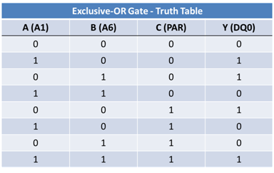
Output Data 0 (DQ0) is a function of three inputs (A1, A6, PAR).
DQ0 = MT0 where MT0 = XOR (A1, A6, PAR)
This means that when there is an odd count of 1s across the three inputs of the XOR gate, the output will go to 1; otherwise, when there is an even count of 1s, the output will go to 0. See Figures 1 and 2.
Figure 1: A 3-input XOR Gate
Figure 2: Truth Table
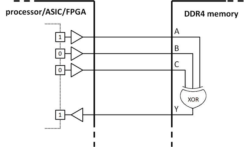
So, the boundary-scan function within the memory controller, which is typically a chip like an FPGA, ASIC, or microprocessor, can be used to stimulate the CT inputs and monitor the CT outputs. Then, using the XOR truth table for evaluating the outputs as a function of the inputs, the interconnects between the memory and the boundary-scan device can be easily tested by the JTAG tool and diagnosed down to net- and pin-level.
This is, of course, invaluable in prototype bring-up when systems don’t boot, or you have other issues that are difficult to diagnose with traditional functional methods. It is also a very fast and accurate test to use during volume manufacturing, since the application of the boundary-scan vectors is very fast, and diagnosis is very accurate and immediate.
Figure 3: Schematic drawing of a memory internconnect with boundary-scan test through DDR4 CT mode
Some platforms where DDR4 memory will be commonly used are those based on the recently unveiled Intel Skylake family. Presuming the boundary-scan function in Skylake processors is suitable to drive the CT inputs and monitor the CT outputs of the DDR4 device that’s in CT mode, then voila! Here is an excellent test tool for early detection of structural faults on the memory buses. No more guessing and headaches.
For more information about memory testing in general and boundary-scan memory test in particular, please take a look at our eBook “How To Test High-Speed Memory With Non-Intrusive Embedded Instruments” or request a demo of the ScanWorks Boundary-Scan Test tools.


