Serial ATA (SATA)-based systems come in a wide range of topologies and trace/cable lengths. This presents signal integrity challenges due to signal loss, reflection and crosstalk; causing SATA device detection problems, lack of interoperability, slower performance, and increased radio frequency interference. What are the main issues, and how do designers mitigate them?
SATA comes in all shapes and sizes. Nowadays, most systems run on a version of SATA revision 3, which provides for a 6Gbps physical layer. There’s a wide array of connectors available, among them mSATA (mini-SATA), eSATA (external SATA), M.2 (previously known as NGFF – Next Generation Form Factor), and SATA Express (which allows for connection to either SATA or PCI Express storage devices). The quality of connectors and cable assemblies can differ substantially from vendor to vendor, and design to design.
All of this presents signal integrity challenges, which can reduce the overall margin of a system. Poor design, configuration, or cable/connector quality can lead to:
- “Device not found” failures
- Poor performance: training to a lower speed, or throughput degradation
- Non-interoperability with certain SATA endpoints
- EMI causing a wireless device, such as a mouse, to work intermittently
The goal is to provide enough “margin headroom” such that SATA-based systems perform optimally even in the presence of adverse conditions. Hardware engineers improve their designs by paying careful attention to equalization tuning and hardware design. These are described below.
Equalization Tuning
SATA uses a fixed programmable (in the BIOS or boot loader) equalization scheme to open the eye and take into account attenuation, reflections and crosstalk in the signal. The challenge here is that each SATA port will be different, based upon its topology, connector type, trace length, and so on. So, what is often missed is that the equalization settings must be programmed differently for each SATA speed, vendor endpoint, port and configuration. This can be done by transmit equalization and/or receive equalization. Equalization must also be tuned based upon the endpoint characteristics, i.e. a given hard disk drive may give off more EMI than a solid state drive. This can be shown in a table:
SATA GenX / Vendor / SSD / HDD:
The host bus adapter (HBA) vendor may have recommendations for the equalization settings for each of these configurations, but it is also worthwhile to make sure that the margins are optimized for each potential vendor configuration per each port.
It should be noted that crosstalk is exacerbated by transmit pre-emphasis and de-emphasis, and receive-side CTLE (continuous-time linear equalization) and FFE (feed-forward equalization) actually amplify crosstalk noise (DFE (decision-feedback equalization), is the only one that doesn't make it worse). And the SATA HBA, unlike for example USB3, does not support adaptive equalization (but redrivers, if present, should). So equalization is not the panacea to make bad margins go away – attention must be paid to good design, connectors, and cable assemblies.
Hardware Design
Since SATA is high-speed, differential and AC-coupled, I/O design guidelines must be followed rigorously. I wrote about an excerpt of these guidelines in my blog here, https://blog.asset-intertech.com/test_data_out/2012/03/high-speed-io-design-guidelines.html, but as mentioned, it is impossible to follow all of the possible design rules.
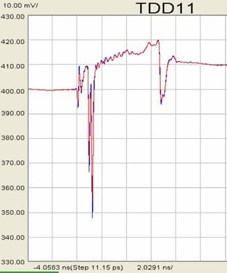
Most importantly, designers should practice stub avoidance, should follow specified trace lengths, and should ensure that intra-pair total length matching is followed. Also, it’s imperative to practice ground voiding directly underneath the SMT pads. If the ground plane directly underneath the SMT pads is not removed, there will be a very strong electrical field between the SMT pad and ground plane below, causing an impedance dip, for example:
In summary, it’s important to use the correct fixed equalization settings to start with, and to follow good design practices. Then, use a methodology like system marginality validation (SMV) to optimize the receive equalization settings for representative sets of device, cable and port combinations. For more technical information on the SMV methodology, check out our white paper here.


